


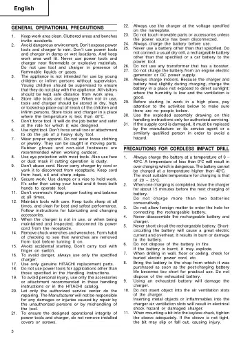

22. Always use the charger at the voltage specified on the nameplate. 23. Do not touch movable parts or accessories unless the power source has been disconnected. 24. Always charge the battery before use. 25. Never use a battery other than that specified. Do not connect a usual dry cell, a rechargeable battery other than that specified or a car battery to the power tool. 26. Do not use any transformer that has a booster. 27. Do not charge the battery from an engine electric generator or DC power supply. 28. Always charge indoors. Because the charger and battery heat slightly during charging, charge the battery in a place not exposed to direct sunlight; where the humidity is low and the ventilation is good. 29. Before starting to work in a high place, pay attention to the activities below to make sure there are no people below. 30. Use the exploded assembly drawing on this handling instructions only for authorized servicing. 31. If the supply cord is damaged, it must be replaced by the manufacture or its service agent or a similarly qualified person in order to avoid a hazard.
1. Keep work area clean. Cluttered areas and benches invite accidents. 2. Avoid dangerous environment. Don’t expose power tools and charger to rain. Don’t use power tools and charger in damp or wet locations. And keep work area well lit. Never use power tools and charger near flammable or explosive materials. Do not use tool and charger in presence of flammable liquids or gases. 3. The appliance is not intended for use by young children or infirm persons without supervision. Young children should be supervised to ensure that they do not play with the appliance. All visitors should be kept safe distance from work area. 4. Store idle tools and charger. When not in use, tools and charger should be stored in dry, high or locked-up place-out of reach of the children and infirm persons. Store tools and charger in a place where the temperature is less than 40°C. 5. Don’t force tool. It will do the job better and safer at the rate for which it was designed. 6. Use right tool. Don’t force small tool or attachment to do the job of a heavy duty tool. 7. Wear proper apparel. Do not wear loose clothing or jewelry. They can be caught in moving parts. Rubber gloves and non-skid footwears are recommended when working outdoor. 8. Use eye protection with most tools. Also use face or dust mask if cutting operation is dusty. 9. Don’t abuse cord. Never carry charger by cord or yank it to disconnect from receptacle. Keep cord from heat, oil and sharp edges. 10. Secure work. Use clamps or a vise to hold work. It’s safer than using your hand and it frees both hands to operate tool. 11. Don’t overreach. Keep proper footing and balance at all times. 12. Maintain tools with care. Keep tools sharp at all times, and clean for best and safest performance. Follow instructions for lubricating and changing accessories. 13. When the charger is not in use, or when being maintained and inspected, disconnect its power cord from the receptacle. 14. Remove chuck wrenches and wrenches. Form habit of checking to see that wrenches are removed from tool before turning it on. 15. Avoid accidental starting. Don’t carry tool with finger on switch. 16. To avoid danger, always use only the specified charger. 17. Use only genuine HITACHI replacement parts. 18. Do not use power tools for applications other than those specified in the Handling Instructions. 19. To avoid personal injury, use only the accessories or attachment recommended in these handling instructions or in the HITACHI catalog. 20. Let only the authorized service center do the repairing. The Manufacturer will not be responsible for any damages or injuries caused by repair by the unauthorized persons or by mishandling of the tool. 21. To ensure the designed operational integrity of power tools and charger, do not remove installed covers or screws.
1. Always charge the battery at a temperature of 0 – 40°C. A temperature of less than 0°C will result in over charging which is dangerous. The battery cannot be charged at a temperature higher than 40°C. The most suitable temperature for charging is that of 20 – 25°C. 2. When one charging is completed, leave the charger for about 15 minutes before the next charging of battery. Do not charge more than two batteries consecutively. 3. Do not allow foreign matter to enter the hole for connecting the rechargeable battery. 4. Never disassemble the rechargeable battery and charger. 5. Never short-circuit the rechargeable battery. Short- circuiting the battery will cause a great electric current and overheat. It results in burn or damage to the battery. 6. Do not dispose of the battery in fire. If the battery is burnt, it may explode. 7. When drilling in wall, floor or ceiling, check for buried electric power cord, etc. 8. Bring the battery to the shop from which it was purchased as soon as the post-charging battery life becomes too short for practical use. Do not dispose of the exhausted battery. 9. Using an exhausted battery will damage the charger. 10. Do not insert object into the air ventilation slots of the charger. Inserting metal objects or inflammables into the charger air ventilation slots will result in electrical shock hazard or damaged charger. 11. When mounting a bit into the keyless chuck, tighten the sleeve adequately. If the sleeve is not tight, the bit may slip or fall out, causing injury.

POWER TOOL
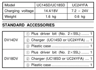
Standard accessories are subject to change without notice.
Optional accessories are subject to change without notice.

Drilling of brick and concrete block, etc. Driving and removing of machine screws, wood
After charging, pull out batteries from the charger first, and then keep the batteries properly.
screws, tapping screws, etc. Drilling of various metals. Drilling of various woods.
Regarding electric discharge in case of new batteries, etc.
As the internal chemical substance of new batteries and batteries that have not been used for an extended period is not activated, the electric discharge might be low when using them the first and second time. This is a temporary phenomenon, and normal time required for recharging will be restored by recharging the batteries 2 – 3 times.
Never short-circuit the battery. 2. Battery installation Insert the battery while observing its polarities (see Fig. 2).
How to make the batteries perform longer.
(1) Recharge the batteries before they become
completely exhausted. When you feel that the power of the tool becomes weaker, stop using the tool and recharge its battery. If you continue to use the tool and exhaust the electric current, the battery may be damaged and its life will become shorter. (2) Avoid recharging at high temperatures.
〈UC14SD/UC18SD〉 Before using the impact drill, charge the battery as follows. 1. Insert the battery into the charger Insert the battery firmly while observing its direction, until it contacts the bottom of the charger (see Figs. 1 and 3). CAUTION
A rechargeable battery will be hot immediately after use. If such a battery is recharged immediately after use, its internal chemical substance will deteriorate, and the battery life will be shortened. Leave the battery and recharge it after it has cooled for a while. 〈UC24YFA〉 Before using the impact drill, charge the battery as follows. 1. Connect the charger’s power cord to a receptacle When the power cord is connected, the charger’s pilot lamp will blink in red. (At 1-second intervals). 2. Insert the battery into the charger Firmly insert the battery into the charger till it contacts the bottom of the charger and checking the polarities as shown in Fig. 3. CAUTION
The UC14SD and UC18SD models are the exclusively designed charger. These cannot charge batteries except the specified batteries. It is possible to insert the batteries other than the specified into the charger and some of them may light up the pilot lamps. However, you are requested to exercise utmost caution not to charge batteries other than specified ones because these can not only be charged but also such actions can result in the malfuntion of chargers. 2. Connect the charger power cord to the receptacle. Connecting the power cord will turn on the charger (the pilot lamp lights up). CAUTION
If the batteries are inserted in the reverse direction, not only recharging will become impossible, but it may also cause problems in the charger such as a deformed recharging terminal. 3. Charging When inserting a battery in the charger, charging will commence and the pilot lamp will light continuously in red. When the battery becomes fully recharged, the pilot lamp will blink in red (At 1-second intervals) (see Table 1). (1) Pilot lamp indication
If the pilot lamp does not light up, pull out the power cord from the receptacle and check the battery mounting condition. About 1 hour is required to fully charge the battery at a temperature of about 20°C. The pilot lamp goes off to indicate that the battery is fully charged. The battery charging time becomes longer when a temperature is low or the voltage of the power source is too low. When the pilot lamp does not go off even if more than two hours have elapsed after starting of the charging, stop the charging and contact your HITACHI AUTHORIZED SERVICE CENTER. CAUTION
The indications of the pilot lamp will be as shown in Table 1, according to the condition of the charger or the rechargeable battery.
If the battery is heated due to direct sunlight, etc., just after operation, the charger pilot lamp may not light up. At that time, cool the battery first, then start charging.

(2) Regarding the temperatures of the rechargeable
Regarding electric discharge in case of new batteries, etc.
battery. The temperatures for rechargeable batteries are as shown in the table below, and batteries that have become hot should be cooled for a while before being recharged.
As the internal chemical substance of new batteries and batteries that have not been used for an extended period is not activated, the electric discharge might be low when using them the first and second time. This is a temporary phenomenon, and normal time required for recharging will be restored by recharging the batteries 2 – 3 times.
Table 2 Recharging ranges of batteries
How to make the batteries perform longer.
(1) Recharge the batteries before they become
completely exhausted. When you feel that the power of the tool becomes weaker, stop using the tool and recharge its battery. If you continue to use the tool and exhaust the electric current, the battery may be damaged and its life will become shorter. (2) Avoid recharging at high temperatures.
(3) Regarding recharging time
Depending on the combination of the charger and batteries, the charging time will become as shown in Table 3.
A rechargeable battery will be hot immediately after use. If such a battery is recharged immediately after use, its internal chemical substance will deteriorate, and the battery life will be shortened. Leave the battery and recharge it after it has cooled for a while. CAUTION If the battery is charged while it is heated because
Table 3 Charging time (At 20°C)
it has been left for a long time in a location subject to direct sunlight or because the batetery has just been used, the pilot lamp of the charger lights up green. In such a case, first let the battery cool, then start charging. When the pilot lamp flickers in red (at 0.2-second
intervals), check for and take out any foreign objects in the charger’s battery installation hole. If there are no foreign objects, it is probable that the battery or charger is malfunctioning. Take it to your authorized Service Center. Since the built-in micro computer takes about 3
The charging time may vary according to temperature and power source voltage. 4. Disconnect the charger’s power cord from the receptacle 5. Hold the charger firmly and pull out the battery NOTE
seconds to confirm that the battery being charged with UC24YFA is taken out, wait for a minimum of 3 seconds before reinserting it to continue charging.
After operation, pull out batteries from the charger first, and then keep the batteries properly.
Table 1

If the battery is reinserted within 3 seconds, the battery may not be properly charged.
the unit is used as drill. While operating the impact drill, take care not to lock the motor. Too long hammering may cause the screw broken
due to excessive tightening. 3. Rotation to Impact changeover (See Fig. 4) The “Rotation (Rotation only)” and “Impact (Impact + Rotation)” can be switched by aligning the drill mark “
” with the triangle mark on the outer body. To make holes in the metal, wood or plastic, switch
” or the hammer mark “
to “Rotation (Rotation only)”. To make holes in bricks or concrete blocks, switch
to “Impact (Impact + Rotation)”. CAUTION
If an operation which is normally performed at the “Rotation” setting is performed at “Impact “ setting, the effect of making holes does not only increase but it may also damage the bit or other parts. 4. Change rotation speed Operate the shift knob to change the rotational speed. Move the shift knob in the direction of the arrow (see Figs. 6 and 7). When the shift knob is set to “LOW”, the drill rotates at a low speed. When set to “HIGH”, the drill rotates at a high speed. CAUTION When changing the rotational speed with the shift
one of the numbers “1, 3, 5 ... 22” on the cap, or the white dots, with the triangle mark on the outer body. (2) When using this unit as a drill, align the cap drill
” with the triangle mark on the outer body. (3) When using this unit as an impact drill, align the
” with the triangle mark on the outer body. CAUTIONS The cap cannot be set between the numerals “1,
cap hammer mark “
3, 5 ... 22” or the white dots. Do not use with the cap numeral between “22” and
the white line at the middle of the drill mark. Doing so may cause damage (See Fig. 5). 2. Tightening torque adjustment (1) Tightening torque
knob, confirm that the switch is off. Changing the speed while the motor is rotating will damage the gears. When setting the shift knob to “HIGH” (high speed)
and the position of the cap is “17” or “22”, it may happen that the clutch does not engaged and that the motor is locked. In such a case, please set the shift knob to “LOW” (low speed). If the motor is locked, immediately turn the power
Tightening torque should correspond in its intensity to the screw diameter. When too strong torque is used, the screw head may be broken or be injured. Be sure to adjust the cap position according to the screw diameter. (2) Tightening torque indication
off. If the motor is locked for a while, the motor or battery may be burnt. 5. The scope and suggestions for uses The usable scope for various types of work based on the mechanical structure of this unit is shown in Table 4.
The tightening torque differs depending on the type of screw and the material being tightened. The unit indicates the tightening torque with the numbers “1, 3, 5 ... 22” on the cap, and a white dots. The tightening toque at position “1” is the weakest and the torque is strongest at the highest number (See Fig. 4). (3) Adjusting the tightening torque
Rotate the cap and line up the numbers “1, 3, 5, ... 22” on the cap, or the white dots, with the triangle mark on the outer body. Adjust the cap in the weak or the strong torque direction according to the torque you need.
mark “ · Table 4

The L-side of the selector button is pushed to turn the bit counterclockwise (See Fig. 9) (The L and
be considered as general standard. As different types of tightening screws and different materials to be tightened are used in actual works proper adjustments are naturally necessary. When using this unit with a machine screw at HIGH
R marks are provided on the body). CAUTION
Always use this unit with clockwise rotation, when using it as an impact drill. 10. Switch operation When the trigger switch is depressed, the tool
(high speed), a screw may damage or a bit may loose due to the tightning torque is too strong. Use this unit at LOW (low speed) when using a machine screw. NOTE
rotates. When the trigger is released, the tool stops. The rotational speed of the drill can be controlled
by varying the amount that the trigger switch is pulled. Speed is low when the trigger switch is pulled slightly and increases as the trigger switch is pulled more. NOTE
The use of the battery EB14H, EB1426H, EB1430H, EB18H, EB1826HL, EB1830H and EB1830HL in a cold condition (below 0 degree Centigrade) can sometimes result in the weakened tightening torque and reduced amount of work. This, however, is a temporary phenomenon, and returns to normal when the battery warms up. 7. Mounting and dismounting of the bit (1) After inserting a driver bit, etc. into the keyless drill
A buzzing noise is produced when the motor is about to rotate; This is only a noise, not a machine failure. 11. For drilling into brick Excessive pressing force never increases drilling speed. It will not only damage the drill tip or reduce working efficiency, but could also shorten the service life of drill bit. Operate the impact drill within 10- 15 kg pressing force while drilling into brick. 12. Using the hook CAUTION When using the hook, pay sufficient attention so
chuck, firmly grasp the ring and tighten the sleeve by turning it toward the right (in the clockwise direction as viewed from the front) (See Fig. 8). If the sleeve becomes loose during operation, tighten it further. The tightening force becomes stronger when the sleeve is tightened additionally. (2) Dismounting the bit
that the main equipment does not fall. If the tool falls, there is a risk of accident. Do not attach the tip tool except phillips bit to the
Firmly grasp the ring and loosen the sleeve by turning it toward the left (in the counter-clockwise direction as viewed from the front) (See Fig. 8). CAUTION
tool main unit when carrying the tool main unit with the hook suspended from a waist belt. Injury may result if you carry the equipment suspended from the waist belt with sharp tipped components such as drill bit attached. The hook can be installed on the right or left side and the angle can be adjusted in 5 steps between 0° and 80°. (1) Operating the hook
When it is no longer possible to loosen the sleeve, use a vise or similar instrument to secure the bit. Set the clutch mode between 1 and 11 and then turn the sleeve to the loose side (left side) while operating the clutch. It should be easy now to loosen the sleeve. 8. Confirm that the battery is mounted correctly 9. Check the rotational direction The bit rotates clockwise (viewed from the rear side) by pushing the R-side of the selector button.
(a) Pull out the hook toward you in the direction
of arrow (A) and turn in the direction of arrow (B) (Fig. 10).
Table 5

(b) The angle can be adjusted in 5 steps (0°, 20°,
40°, 60°, 80°). Adjust the angle of the hook to the desired position for use. (2) Switching the hook position CAUTION
Repair, modification and inspection of Hitachi Power Tools must be carried out by an Hitachi Authorized Service Center. This Parts List will be helpful if presented with the tool to the Hitachi Authorized Service Center when requesting repair or other maintenance. In the operation and maintenance of power tools, the safety regulations and standards prescribed in each country must be observed. MODIFICATIONS
Incomplete installation of the hook may result in bodily injury when used. (a) Securely hold the main unit and remove the
screw using a slotted head screwdriver or a coin (Fig. 11). (b) Remove the hook and spring (Fig. 12). (c) Install the hook and spring on the other side and
Hitachi Power Tools are constantly being improved and modified to incorporate the latest technological advancements. Accordingly, some parts (i.e. code numbers and/or design) may be changed without prior notice.
securely fasten with screw (Fig. 13). NOTE
Pay attention to the spring orientation. Install the spring with larger diameter away from you (Fig. 13). (3) Using the bit holder
Installing the bit
Slide the bit from the side in the direction of Fig. 14, and then insert firmly until the groove on the bit locks in the protruded section of the hook. Removing the bit
Securely hold the main unit and pull out the bit by holding the tip with your thumb (Fig. 15). CAUTION The bit may come loose from the hook and cause
Blue: – Neutral Brown: – Live As the colours of the wires in the mains lead of this tool may not correspond with the coloured markings identifying the terminals in your plug proceed as follows: The wire coloured blue must be connected to the terminal marked with the letter N or coloured black. The wire coloured brown must be connected to the terminal marked with the letter L or coloured red. Neither core must be connected to the earth terminal. NOTE This requirement is provided according to BRITISH STANDARD 2769: 1984. Therefore, the letter code and colour code may not be applicable to other markets except United Kingdom.
bodily injury when reversing the direction of the bit as shown in Fig. 14 or when using the driver with the bit stored incomplete. Only Hitachi STANDARD ACCESSORIES phillips bit
(No. 2 × 55L; Code No. 318236) may be used. Do not use other bits since they may come loose.
1. Inspecting the tool Since use of as dull tool will degrade efficiency and cause possible motor malfunction, sharpen or replace the tool as soon as abrasion is noted. 2. Inspecting the mounting screws Regularly inspect all mounting screws and ensure that they are properly tightened. Should any of the screws be loose, retighten them immediately. Failure to do so could result in serious hazard. 3. Cleaning on the outside When the impact drill is stained, wipe with a soft dry cloth or a cloth moistened with soapy water. Do not use chloric solvents, gasoline or paint thinner, for they melt plastics. 4. Storage Store the impact drill in a place in which the tempera ture is less than 40°C and out of reach of children. 5. Service parts list A : Item No. B : Code No. C : No. Used D : Remarks
Information concerning airborne noise and vibration The measured values were determined according to EN50144.
The typical A-weighted sound pressure level: 89 dB (A). The typical A-weighted sound power level: 102 dB (A). Wear ear protection.
The typical weighted root mean square acceleration value: 7.7 m/s2.
Besitzer und unser Team antworten in der Regel innerhalb eines Tages – und Ihre Frage hilft auch anderen weiter.
Stellen Sie die erste Frage — andere Nutzer oder unser Team antworten Ihnen.