



Please read this manual carefully and completely before you use the device for the first time. The device may only be used by qualified personnel and repaired by PCE Instruments personnel. Damage or injuries caused by non-observance of the manual are excluded from our liability and not covered by our warranty.

2.1 Device
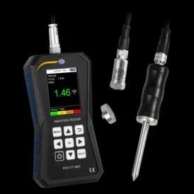
The vibration meters PCE-VT 3800 and PCE-VT 3900 are capable of measuring and monitoring vibration in machine components. The measuring units include vibration acceleration, vibration velocity and vibration displacement. The reading for the set measuring unit can be shown as RMS, peak, peak-peak value or crest factor. These measured values can be used, for instance, to detect machine imbalances and arising bearing damage. Apart from a Hold function which freezes the current measurement value, the device also has a function to show the maximum value. During a measurement, this function displays the highest value measured so far in addition to the current measurement value. Another feature is the automatic evaluation of the measurement value with regards to the ISO standard 10816-3. When this feature is enabled, the current measurement value is classified into one of four defined zones in line with the corresponding limit values and highlighted by a colour. Other features of the PCE-VT 3800 include a memory for manual measurements and a data logger function for recording measured values over a longer period of time. In addition to the features described above, the PCE-VT 3900 offers functions for route measurement, calculation of FFT and RPM measurement. With the PC software included in the scope of delivery, the saved data can be imported from the meter and displayed, evaluated and archived accordingly. The meters have an internal LiPo battery that is charged via the USB socket with a common USB mains adaptor and the battery life is approx.15 ... 20 hours, depending on the set brightness.


Fig. 29 Description of PCE-VT 3800/3900

2.2 Function keys


2.3 Display (measurement screen)
Fig. 1 Measurement screen

3.1 Technical specifications
Vibration meter PCE-VT 3800/3900
Vibration acceleration 0.0 … 399.9 m/s² Vibration velocity 0.0 … 399.9 mm/s Vibration displacement 0.0 … 3.9 mm
Parameters RMS, peak, peak-peak, crest factor
Accuracy Reference frequency 160 Hz ±2 %
Vibration acceleration 0.1 m/s² Vibration velocity 0.1 mm/s Vibration displacement 1.0 µm
Vibration acceleration 10 Hz … 10 kHz Vibration acceleration 1 kHz … 10 kHz Vibration velocity 10 Hz … 1 kHz Vibration displacement 10 Hz … 200 Hz
Manual storage 99 folders with 50 memory items each
Various start/stop triggers Measuring interval 1 s … 12 h 50 memory items (up to 43200 readings per measurement)
100 routes configurable via PC software Up to 100 machines per route, up to 100 measuring spots possible each 1000 readings per measuring spot
Route measurement (PCE-VT 3900 only)
FFT (PCE-VT 3900 only)
RPM measurement (PCE-VT 3900 only) 600 … 50000 RPM
Units Metric / imperial


Menu languages English, German, French, Spanish, Italian, Dutch, Portuguese, Turkish, Polish, Russian, Chinese, Japanese
Battery life Approx. 15 … 20 h (depending on display brightness)
Dimensions Ø 17 x 46 mm (PCE-VT 3xxx SENSOR) Ø 29 x 81 mm (PCE-VT 3xxxS SENSOR)
Weight (without cable) 52 g (PCE-VT 3xxx SENSOR) 119 g (PCE-VT 3xxxS SENSOR)
3.2 Delivery contents

3.3 Accessories
3.3.1 PCE-VT 3xxx MAGNET 25

The magnet adaptor PCE-VT-3xxx MAGNET 25 can be used to attach the vibration sensor to magnetic measuring spots.
3.3.2 PCE-VT 3xxxS SENSOR

To make quick measurements at locations which are difficult to access, the handle with an integrated vibration sensor PCE-VT 3xxxS SENSOR can be used in conjunction with the measuring tip PCE-VT-NP.
3.3.3 Measuring tip PCE-VT-NP

Hard-to-access measurement locations can be reached with the measuring tip PCE-VT-NP. The measuring tip should be placed as vertically as possible on the measurement surface in order to achieve accurate measurements.
3.3.4 USB mains adaptor NET-USB-EU
With the USB mains adaptor, the meter can be charged and operated.


3.3.5 Vibration calibrator PCE-VC20 / PCE-VC21

The vibration meter PCE-VT 3800 / 3900 can be calibrated with the vibration calibrators PCE-VC20 or PCE-VC21.
3.3.6 Instrument case PCE-VT CASE

The instrument case is used for safe storage and transport of the vibration meter and its accessories.

4.1 Power supply
An internal rechargeable LiPo battery is used to power the vibration meter. With a fully charged battery and depending on the display brightness, a battery life of approx. 15 … 20 h is possible. The battery is charged via the USB port at the bottom of the meter, using a USB charger. The charging process can be shortened by switching off the meter while charging. The current battery level is displayed in the status bar in the top right corner of the screen. If the battery charge is insufficient for proper operation of the device, the device automatically powers off and the display below is shown.

Fig. 2 Automatic power off
4.2 Preparation
Connect the sensor with the spiral cable to the vibration meter before turning it on and connect the other end of the cable with the sensor connector of the meter. Tighten the knurled nut to ensure proper connection. The meter recognizes the sensor automatically. If no sensor is connected, “No sensor” will be displayed instead of the reading in the different measuring functions and the corresponding memory functions are deactivated. This indication also helps diagnosing cable breakage. In order to turn on the device, press the ON/OFF key until the screen backlight turns on and the start-up screen is shown. The start-up screen is shown for about 2 seconds and the device automatically switches to the measurement screen afterwards. The device is turned off by pressing the ON/OFF key until the screen turns off. The following icon is displayed on the start- up screen if date and time need to be set:


Fig. 3 Set date and time
The main menu can be reached from any screen by pressing the MENU key. The arrow keys are used to navigate through the menu items which can be activated with the OK key. The BACK key is used to return from sub menus. The main menu of the PCE-VT 3800 consists of the sub menus Measurement, Data logger, Memory, Settings, Calibration, Manual and Info which are explained in detail below.
5.1 Measurement
The sub menu Measurement is used to configure the different options relevant for the measurement: Measuring unit, Parameter, ISO evaluation, Display max value.
5.1.1 Measuring unit
The measuring unit and the respective frequency range can be adjusted in this menu. The options include acceleration a (10 Hz … 10 kHz), acceleration a (1 kHz … 10 kHz), velocity v (10 Hz … 1 kHz) and displacement d (10 Hz … 200 Hz). This sub menu can also be directly accessed from the main screen by pressing the arrow key LEFT.

Fig. 4 Measuring unit

5.1.2 Parameter
It is possible to switch between the parameters RMS, peak, peak-peak and crest factor. This sub menu can also be directly accessed from the main screen by pressing the arrow key RIGHT.

Fig. 5 Parameter
5.1.3 ISO evaluation
In order to enable the automatic evaluation of the current measurement value according to the ISO standard 10816-3, the measuring unit vibration acceleration or vibration velocity in conjunction with the parameter RMS must be selected. This is necessary as the ISO standard only lists valid thresholds for these combinations. After selecting the correct options, the appropriate group for the machine can be selected in this menu. The reading will be evaluated according to this group. When this function is enabled, the name of the activated group is displayed at the bottom of the measuring screen together with a graph of the four vibration severity zones. The current measurement value is categorized into one of the four zones and colour coded according to the thresholds. Additionally, the item which represents the current zone flashes so that the reading can be quickly evaluated with regards to the limit values defined in the standard. If the ISO evaluation is currently enabled and an incompatible measuring unit (acceleration) or parameter (peak, peak-peak, crest factor) is selected, the evaluation function is automatically disabled and a hint is displayed on the screen.


Fig. 6 Hint ISO evaluation disabled
As described previously, the ISO evaluation function requires the measuring unit velocity or displacement in conjunction with the parameter RMS. Otherwise, the menu to enable this function cannot be opened and the following hint is displayed on the screen.

Fig. 7 Hint for activation of ISO evaluation
Machine groups:

Group 2 Vibration velocity Group 1
mm/s in/s rigid flexible rigid flexible > 11.0 > 0.43 D 7.1 ... 11.0 0.28 ... 0.43 C 4.5 ... 7.1 0.18 ... 0.28 C C 3.5 ... 4.5 0.14 ... 0.18 2.8 ... 3.5 0.11 ... 0.14 2.3 ... 2.8 0.09 ... 0.11 1.4 ... 2.3 0.06 ... 0.09 < 1.4 < 0.06 A
D D
B
B C B
A B A A
Vibration severity zones for vibration velocity according to DIN ISO 10816-3

Vibration severity zones for vibration displacement according to DIN ISO 10816-3
5.1.4 Display max value
This sub menu is used to activate the display of the max value. When enabled, the highest reading so far is displayed separately below the current measurement value. The BACK key can be used to reset the max value.
5.2 Data logger
In this menu, the data logger can be started and the data logger settings can be changed.
5.2.1 Start data logger
The data logger is started via this sub menu which opens the data logger screen where the current measuring parameters, the reading and the data logger settings are displayed. For the data logger, the same settings as for the general measuring mode are used. These can be changed as described under 5.1 Measurement.

5.2.2 Measuring interval
For the measuring interval, various intervals between 1 s and 12 h are possible.
5.2.3 Start condition
The data logger can either be started manually by a keystroke or automatically at a certain date which is set in this menu.
5.2.4 Stop condition
There are three different options for stopping the data logger. You can either stop the data logger manually by a keystroke, at a certain date or after a set time interval.
5.2.5 Delete data / Delete all
Via these two menu items, either individual data records or all saved data records can be deleted at a time.
5.3 Memory
When manual memory is enabled, individual measurements can be saved to the internal memory for later viewing.
5.3.1 Select folder
Here, the current folder for the memory can be selected. A total of 99 folders for 50 individual measurements each is available.
5.3.2 Display data
With the help of these functions, the measurements saved in the currently selected folder can be viewed again.
5.3.3 Delete data / Delete folder / Delete all
These menu items are used to delete an individual measurement or all measurements in the current folder or all measurements in all folders.
5.4 Route measurement (PCE-VT 3900 only)
This menu is used to start saved routes and to display or delete readings belonging to the routes.
5.4.1 Start route
The routes must be configured using the PC software and transferred to the meter. After the routes have been transferred to the device, a single route can be selected and started with this menu item.

5.4.2 Display data
This menu is used to display saved readings from the measuring spots of a route. The navigation has a tree structure and the order is identical to the route configuration when created with the PC software.
5.4.3 Delete all
Via this menu item, all measured values from the respective measuring spots of all routes can be deleted. The routes themselves will remain.
5.5 FFT (PCE-VT 3900 only)
In this menu, the FFT function can be started and saved FFT spectra can be displayed and deleted.
5.5.1 FFT acceleration / FFT velocity
The spectrum can be displayed either for the vibration acceleration or for the vibration velocity.
With the help of this function, a machine revolution speed can be entered. This value is saved when a spectrum is saved and is also displayed after the transfer to the PC software. In addition, the integer harmonics of the entered machine speed can be displayed in the spectrum for orientation. The number of harmonics to be displayed can be set from 1 (machine speed only) to a maximum of 11. If the function "Show harmonics" is activated in the meter, the harmonics with the parameters set here are displayed in the zoom spectrum as red dashed lines with numbering during the FFT analysis.
5.5.3 Display data
With the help of this function, saved FFT spectra can be viewed again.
5.5.4 Delete data / Delete all
These two menu items can be used to delete individual FFT spectra or all saved spectra at a time.
5.6 RPM measurement (PCE-VT 3900 only)
Via this menu item, the RPM measurement can be started. This function has no further settings.

5.7 Calibration
A vibration calibrator capable of generating a reference vibration of 10 mm/s RMS at 159.2 Hz (e. g. PCE-VC20 or PCE-VC21) is required for the calibration of the vibration meter. The calibration can be started via the sub menu Calibration. A code is required to enter this menu in order to prevent an inadvertent overwrite of the current calibration. The required code is 1402.

Fig. 8 Code request
After the code request, the required reference vibration is indicated. The sensor of the vibration meter must now be mounted on the vibration calibrator.

Fig. 10 Hint for required reference vibration
After turning on the vibration calibrator and, if required, setting the reference vibration, the hint can be confirmed with the OK key so that the calibration screen opens. This screen shows the required characteristic values of the reference vibration and the current measurement value in green font and in the unit mm/s. It is not necessary to adjust the measuring unit and the parameter specifically for the calibration as only the RMS value of the vibration velocity will be evaluated during this procedure.


Fig. 11 Calibration screen
Fig. 12 Confirmation dialogue
The calibration is performed automatically and should take only a few seconds. After a successful calibration, the hint “Calibration successful” pops up. The device then returns to the measurement screen.
5.8 Settings
5.8.1 Units
In the sub menu Units, you can choose either the International System of Units (SI) or the Anglo- American unit system (US).
5.8.2 Decimal separator
As decimal separator for the readings, you can either select a dot or a comma.
5.8.3 Date & time
This menu is used to change the date and time. The date format can also be changed.

5.8.4 Brightness
In this tab, the display brightness can be adjusted from 10 % to 100 %. Automatic dimming can also be set. After a set time, the display will be dimmed to a lower brightness in order to save energy. Pressing any key will set the brightness back to its original value.
5.8.5 Language
This menu is used to switch between different menu languages. The available languages are English, German, French, Spanish, Italian, Dutch, Portuguese, Turkish, Polish, Russian, Chinese and Japanese.
5.8.6 Auto power off
This option enables the auto power off function. The available time periods are 1 minute, 5 minutes and 15 minutes. After the set time period has elapsed, the device will automatically turn off and pressing any key will reset the timer. It is also possible to disable the auto power off function.
5.8.7 Reset
This menu is used to reset the device to its factory settings. Device settings are separate from the calibration and each can be reset individually by selecting the corresponding menu item. A reset of the device settings will load default values for the measurement parameters and any remaining menu options. A calibration which may have been performed beforehand is retained. In order to prevent an inadvertent reset of the calibration, a code is required to enter this menu. The code is the same as for the calibration itself: 1402.

Fig. 13 Code request
Fig. 14 Confirmation dialogue

5.9 Manual
This menu shows a QR code. This code can be decoded with a suitable scanner like, for example, a mobile phone and it links directly to this manual.
5.10 Info
This menu shows the device name and firmware version.
6.1 Measurement screen
After turning on the device, the measurement screen is displayed. The sensor converts the continuously recorded mechanical vibration into an electrical signal which is subsequently evaluated according to the set parameters and displayed as a measured value. When the meter is started for the first time and after resetting the device settings, the display shows the RMS value of the measured vibration velocity in mm/s. When measurement parameters are adjusted via the menu, the changed settings are applied and displayed when returning to measurement mode. These will also remain when the meter is turned off and back on. The menus for the measuring unit and the parameters can also be accessed directly from the measuring screen, by using the arrow keys LEFT or RIGHT .

Fig. 15 Measurement screen
6.2 Preparation for the measurement
Before making a measurement, the desired measurement parameters must be set in the menu. These include the measuring unit, the parameter, the unit and, depending on the application, the ISO evaluation or max value.

6.3 Making a measurement
To make a measurement, the sensor must be attached to the desired measuring spot using a stud bolt or the magnetic adaptor. When measuring with the optionally available measuring tip, ensure correct alignment. In measuring mode, the measurement is carried out continuously and the current value is displayed on the screen. If ISO evaluation is activated, the measured value is automatically assigned to the corresponding zone on the basis of the selected grouping and highlighted in colour so that a quick assessment of the vibration severity is possible. In addition, the corresponding zone flashes periodically.
6.4 Memory
By pressing the OK key while the measurement screen is opened, the current measured value can be saved. This is confirmed by a corresponding message at the bottom of the screen. A folder number and the measured value index are displayed. The measured value is displayed in the currently selected folder which can be selected via the menu. A total of 99 folders with 50 readings each is available. If the maximum number of measurements is already saved in a folder, a message is displayed when an attempt is made to save another measurement. In this case, a different folder can be selected or saved measurements can be deleted. The saved measurements can be viewed again via the menu item Memory > Display data.

Fig. 30 Manual memory
The desired folder must be set beforehand via the corresponding menu. The measurements can also be read out with the PC software.
Saved measurements can be deleted either individually, completely for the current folder or completely for all folders via the corresponding menu items.

With the help of the data logger function, measured values can be logged over a defined period of time. A total of 50 memory locations is available for the saved data records. The PC software must be used to display the data records.
7.1 Settings
The same settings are used for the measurement parameters as for the regular measurement mode. These can be set in the Measurement menu. The settings specific to data logger mode are in the Data logger menu.

Fig. 31 Data logger
The storage interval can be set between 1 s ... 12 h. This means that only the measured values within the set interval are saved. The measured value display during logging updates at the same rate as in regular measuring mode. The data logger can be started in two different ways: either manually via the OK key or a start time can be set via the Start condition menu. There are three different options for stopping the data logger. These can be selected via the Stop condition menu. It can be stopped manually by pressing the OK key, at a specific time or after a configurable time interval. The start and stop conditions can be combined in any way. When selecting date/time as the start or stop condition, the start of the data logger is prevented if the set start/stop time is before the current time or if the stop time is before the start time. In this case, the corresponding settings must be checked and corrected. After the desired data logger settings have been selected, the data logger can be started.

7.2 Measurement
The data logger is started via the menu item Start data logger, which leads to the data logger screen. This screen shows the current measurement parameters, the measured value and the data logger settings.

Fig. 32 Data logger screen
Depending on the start condition, the data logger starts automatically when the set start time has been reached (if set) or the OK key must be pressed to start the data logger. An active measurement is indicated by REC in the upper right corner of the screen as well as a flashing red circle. Depending on the set stop condition, the data logger stops either automatically after reaching the stop time or after the desired duration or after pressing the OK key. Even if a time or duration has been set as the stop condition, an ongoing measurement can always be stopped by pressing the OK key. Depending on the duration of the recording, make sure that the battery is sufficiently charged. The device can also be operated with the USB charger so that measurements can be made over a long period of time. A successful measurement is confirmed by a corresponding message at the bottom of the screen. At the same time, the start time is displayed for identification purposes. The data records can then be read out from the meter and displayed with the PC software.
8 Route measurement (PCE-VT 3900 only) With the help of the route measurement, a regular check is made possible by measuring numerous measuring spots in a certain sequence. The configuration of a route must be done via the PC software, which is described in detail in the corresponding manual. A route has a tree structure: Thus, up to 100 machines can be assigned to a single route in the first level and up to 100 measuring spots to each individual machine in the second level. In total, up to 100 different routes can be configured. The names of the individual route elements can be freely assigned in the PC software. For each measuring spot, up to 1000 measured values can be saved to enable a trend display.

8.1 Start route
After transferring a route to the meter, it can be selected and started via the menu item Start route.

Fig. 33 Menu route measurement
The display shows the name of the route in the upper right corner. To the right of this, there is a percentage figure representing the total progress of the current route measurement. For each recorded measurement, the percentage display changes accordingly. Below this, the currently selected machine or measuring spot name and the measuring parameters for this measuring spot are displayed.

Fig. 34 Route measurement
Use the arrow keys LEFT / RIGHT to select the measuring spots and press the OK key to save a measurement. The order of the machines and measuring spots can be changed when configuring the route in the PC software. If no measured value has yet been recorded for a measuring spot, the name appears in red and changes to green after a measurement. Similarly, the name of a machine appears in red if a measurement has not yet been taken for all associated measuring spots.


Fig. 35 Measurement made
For a measurement already made at a measuring spot, a measurement can be repeated, which overwrites the previous reading and must be confirmed in the corresponding dialogue window.

Fig. 36 Overwrite measurement of a measuring spot
for current route measurement
As soon as a measured value has been recorded for all measuring spots, the following dialogue window appears.

Fig. 37 Route measurement completed

If the red X is selected, the route is not yet completed and measurements for previous measuring spots can be overwritten, for example. When the green tick is selected, this route is completed so that it restarts when selected again.
8.2 Cancel or interrupt route
It is possible to interrupt a route that has been started and continue it at a later time. This means that the progress and the already recorded measuring spots remain. When the BACK key or the MENU key is pressed, the following dialogue window appears:

Fig. 38 Cancel or interrupt route
Selecting the red X interrupts the route and returns to the menu. Selecting the green tick serves to prematurely complete a route that has not yet been completely measured so that this route starts again from the beginning when selected again. If a route has not yet been completed and is selected again, the following dialogue box appears. This dialogue also appears if the meter is switched off during a route measurement.

Fig. 39 Start new route or continue previous session
To continue the route, the red X must be selected again. This retains the previous progress. If the green tick is selected, the route is restarted with 0 % progress.

8.3 Display data
Via the menu item Display data, the individual measuring spots can be selected and the measured values can be displayed. The measuring spot name is displayed in the title and the measuring parameters of this measuring spot are displayed below it. The measured values recorded during the route measurement are displayed in the list below sorted by date and can be scrolled through with the UP / DOWN arrow keys. In addition, the measured values can be imported with the PC software and displayed graphically.
8.4 Delete data
Use the menu item Delete all to delete all saved measured values from all measuring spots. The routes themselves remain. In addition, the measured values can also be deleted via the PC software.
The FFT analysis is used to display the vibration signal in the frequency range. Thus, either the amplitudes of the vibration acceleration or of the vibration velocity can be displayed in dependence on the frequency. With the FFT analysis, 2048 frequency lines are calculated and different frequency resolutions are possible depending on the maximum frequency of the spectrum.
9.1 Operation and display
In the FFT menu, the desired measuring mode – either vibration acceleration or vibration velocity – must be selected.

Fig. 40 FFT menu
The selected mode appears at the top left of the display and the current frequency resolution dF is shown to the right. The frequency resolution dF depends on the maximum frequency of the spectrum and the following settings are possible for vibration acceleration:
Max. frequency Frequency resolution dF 7812 Hz 3.8 Hz 3906 Hz 1.9 Hz 1953 Hz 1.0 Hz 976 Hz 0.5 Hz

For vibration velocity, only the setting dF 0.5 Hz with a max. frequency of 976 Hz is possible. The different frequency ranges can be changed with the arrow keys UP and DOWN.

Fig. 41 FFT screen
Two spectra are shown in the display. The upper spectrum shows an overall view in which the 2048 FFT lines are averaged. The frequency range is displayed below the graph. The lower spectrum Zoom shows the FFT lines without averaging. Due to the screen resolution, only one section of the entire spectrum can be displayed at a time. The section displayed in the zoom view is represented in the overall view by an orange rectangle and the current frequency range is displayed below the spectrum as in the overall view. Above the overall view, the measured value and the frequency of the FFT line with the highest amplitude are displayed in green font. In addition, the maximum in both spectra is shown as a green line. The cursor is operated with the LEFT / RIGHT arrow keys. This displays the amplitude and frequency of the selected FFT line in orange font colour above the zoom view. In the two spectra, the current cursor position is represented by an orange dashed line. With the help of the HOLD key, the current spectrum can be held. This is indicated by the message HOLD in the overall view at the top right. Pressing it again leads back to the live measurement.

This menu can be used to set how a machine speed and its harmonics are displayed as auxiliary lines in the spectrum. To do this, the RPM and the desired number of harmonics must first be set. The first harmonic represents the fundamental frequency. Up to 11 harmonics can be selected which are displayed in the zoom spectrum as red dashed lines and numbered accordingly. If the function "Show harmonics" is activated, the harmonics with the parameters set here are displayed in the zoom spectrum as red dashed lines with numbering during the FFT analysis. This function can also be used to quickly deactivate the display without having to change the RPM settings.

Fig. 42 Display of harmonics
9.3 Memory
The current spectrum can be saved by pressing the OK key. Saving is confirmed by a message at the bottom of the screen indicating the time for identification. If a machine speed has been entered, this is also saved and displayed in the statistics field after the transfer with the PC software. Saved spectra can be reviewed via the Display data menu. The display and operation are identical to a regular live measurement. The measurements can either be removed individually with Delete data or completely with Delete all.
With this function, the maximum amplitude of the vibration velocity in the measured vibration signal is determined and the corresponding frequency is displayed as RPM and in Hz. Note Faulty measurements may occur if there are any interfering factors in the signal at other frequencies.

With the help of the PC software PCE-VT 3xxx, the saved data of the different measuring functions (manual memory, data logger, route measurement, FFT) can be transferred from the meter to the PC, displayed and archived. The configuration of the routes for the route measurements is only possible via the software. The functions of the PC software are described in a separate manual
which can be accessed directly in the programme via the button.
You can read our warranty terms in our General Business Terms which you can find here: https://www.pce-instruments.com/english/terms
For the disposal of batteries in the EU, the 2006/66/EC directive of the European Parliament applies. Due to the contained pollutants, batteries must not be disposed of as household waste. They must be given to collection points designed for that purpose. In order to comply with the EU directive 2012/19/EU we take our devices back. We either re-use them or give them to a recycling company which disposes of the devices in line with law. For countries outside the EU, batteries and devices should be disposed of in accordance with your local waste regulations. If you have any questions, please contact PCE Instruments.

PCE Deutschland GmbH PCE Instruments France EURL PCE Ibérica S.L. Im Langel 4 23, rue de Strasbourg Calle Mayor, 53 D-59872 Meschede 67250 Soultz-Sous-Forets 02500 Tobarra (Albacete) Deutschland France España Tel.: +49 (0) 2903 976 99 0 Téléphone: +33 (0) 972 3537 17 Tel. : +34 967 543 548 Fax: +49 (0) 2903 976 99 29 Numéro de fax: +33 (0) 972 3537 18 Fax: +34 967 543 542 info@pce-instruments.com [email protected] [email protected] www.pce-instruments.com/deutsch www.pce-instruments.com/french www.pce-instruments.com/espanol United Kingdom Italy Turkey
PCE Instruments UK Ltd PCE Italia s.r.l. PCE Teknik Cihazları Ltd.Şti. Unit 11 Southpoint Business Park Via Pesciatina 878 / B-Interno 6 Halkalı Merkez Mah. Ensign Way, Southampton 55010 Loc. Gragnano Pehlivan Sok. No.6/C Hampshire Capannori (Lucca) 34303 Küçükçekmece - İstanbul United Kingdom, SO31 4RF Italia Türkiye Tel: +44 (0) 2380 98703 0 Telefono: +39 0583 975 114 Tel: 0212 471 11 47 Fax: +44 (0) 2380 98703 9 Fax: +39 0583 974 824 Faks: 0212 705 53 93 info@pce-instruments.co.uk [email protected] info@pce-cihazlari.com.tr www.pce-instruments.com/english www.pce-instruments.com/italiano www.pce-instruments.com/turkish The Netherlands Hong Kong United States of America
PCE Brookhuis B.V. PCE Instruments HK Ltd. PCE Americas Inc. Institutenweg 15 Unit J, 21/F., COS Centre 1201 Jupiter Park Drive, Suite 8 7521 PH Enschede 56 Tsun Yip Street Jupiter / Palm Beach Nederland Kwun Tong 33458 FL Telefoon: +31 (0)53 737 01 92 Kowloon, Hong Kong USA [email protected] Tel: +852-301-84912 Tel: +1 (561) 320-9162 www.pce-instruments.com/dutch jyi@pce-instruments.com Fax: +1 (561) 320-9176 www.pce-instruments.cn info@pce-americas.com
Germany France Spain


User manuals in various languages (français, italiano, español, português, nederlands, türk, polski, русский, 中文) can be found by
Specifications are subject to change without notice.
Besitzer und unser Team antworten in der Regel innerhalb eines Tages – und Ihre Frage hilft auch anderen weiter.
Stellen Sie die erste Frage — andere Nutzer oder unser Team antworten Ihnen.